Home » Without Label » Contrl Wiring Diagram Of Star Delta Starter : Image result for Gif image of star delta starter | Delta ... / And their applications with advantages.
Contrl Wiring Diagram Of Star Delta Starter : Image result for Gif image of star delta starter | Delta ... / And their applications with advantages.
Contrl Wiring Diagram Of Star Delta Starter : Image result for Gif image of star delta starter | Delta ... / And their applications with advantages.. Star delta starters consist of a power circuit and control circuit. If the motor is too heavily loaded, there will not for star delta starter circuit diagram,wiring technique and motor base termination,please read my post for star delta… 15 star delta starter control circuit diagram. If you want to find the other picture or article about motor control panel. A 8 pin timer are used.
A star delta starter is the most commonly used method for the starting of a 3 phase induction motor. Next, the circuit goes through the nc terminals of the thermal over load relay. The on delay timer diagram is also shown in the diagram. As shown in the fig. Star delta starters consist of a power circuit and control circuit.
STAR-DELTA CONTROL DIAGRAM WITH MOTOR POWER CONNECTION from 1.bp.blogspot.com Next, the circuit goes through the nc terminals of the thermal over load relay. When the fault occurs the thermal overload relay will trip the circuit. Refer to the below star delta circuit, In the above star delta starter control circuit wiring diagram with timer and normally close push button/normally open push button switch. And their applications with advantages. Here you can see the control circuit diagram of automatic star delta starter. A star delta starter is the most commonly used method for the starting of a 3 phase induction motor. The control circuit uses to control the starter circuit such as on, off and tripping operations.
Motor control panel wiring diagram pdf star delta starter electrical notes articles is one of the pictures that are related to the picture before in the collection gallery, uploaded by autocardesign.org.you can also look for some pictures that related to wiring diagram by scroll down to collection on below this picture.
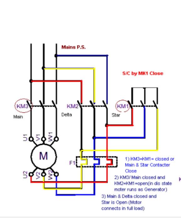
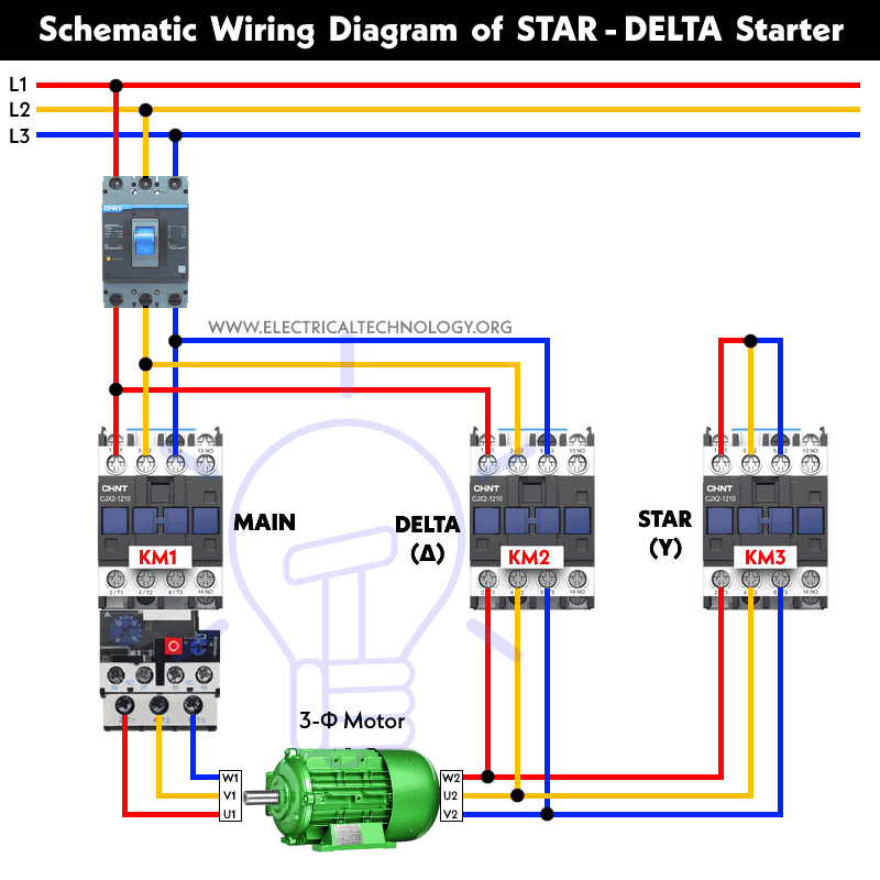
How to wire star delta starter with three phase ac motors? Star delta connection circuit diagram: Star delta starters consist of a power circuit and control circuit. A 8 pin timer are used. Here you can see the control circuit diagram of automatic star delta starter. Star delta starter diagram with connection of 3 phase motor and control circuit wiring. Star delta wiring diagram with timer are listed below. If you want to find the other picture or article about motor control panel. R , y, b = red, yellow, blue ( 3 phase lines)c.b = general circuit breakermain = mai supplyy = starδ = deltac1, c2, c3 = contatcors (power diagram)o/l = over load relayno = normally opennc = normally closed k1 = contactor (contactor coil) k1/no = contactor holding coil. How to wire star delta starter with three phase ac motors? Star delta starting and auto transformer starting. Connect a thermal overload relay with the main contactor as shown in the above diagram. The on delay timer diagram is also shown in the diagram.
When the fault occurs the thermal overload relay will trip the circuit. A wiring diagram usually gives opinion just about the relative point and concord of. Dosto aaj ki is video me aap dekheenge star delta starter control circuit diagram or kaise kaam karta hai #stardeltastartercircuitsubscribe yk electrical for. And their applications with advantages. The control circuit uses to control the starter circuit such as on, off and tripping operations.
Star Delta Motor Starter Wiring Diagram Pdf - Database ... from i0.wp.com Power and #control circuit.star delta starter control circuit #diagram star delta control circuit s. The on delay timer diagram is also shown in the diagram. The on delay timer diagram is also shown in the diagram. Refer to the below star delta circuit, How to wire star delta starter with three phase ac motors? Star delta starter diagram with connection of 3 phase motor and control circuit wiring. Most induction motors are started directly on line, but when very large motors are started that way, they cause a disturbance of voltage on the supply lines due to large starting curr… In the above star delta starter control circuit wiring diagram with timer and normally close push buttonnormally open push button switch.
If the motor is too heavily loaded, there will not for star delta starter circuit diagram,wiring technique and motor base termination,please read my post for star delta…
And also i will explain this starter connection step by ste. If the motor is too heavily loaded, there will not for star delta starter circuit diagram,wiring technique and motor base termination,please read my post for star delta… Connect those all terminal with the motor as shown in the above diagram. In control wiring diagram all magnetic contactors coils are rated 220 vac. Star delta wiring diagram with timer pdf. The on delay timer diagram is also shown in the diagram. Control wiring diagram of star delta starter free. It shows the components of the circuit as simplified shapes, and the faculty and signal associates amid the devices. Star delta starter wiring diagram, this post is about the main wiring connection of three phase motor with star delta starter and control wiring diagram of 1 mccb circuit breaker 3 magnetic contactors 3 phase motor thermal overload relay / electronic overload relay ocr an on daily timer (8 pin timer. One is power circuit and another one is control circuit. Most induction motors are started directly on line, but when very large motors are started that way, they cause a disturbance of voltage on the supply lines due to large starting curr… Star delta starting and auto transformer starting. Have been dealt with in chapter viii.
15 star delta starter control circuit diagram. Star delta starters consist of a power circuit and control circuit. A wiring diagram usually gives opinion just about the relative point and concord of. In control wiring diagram all magnetic contactors coils are rated 220 vac. Star delta starting and auto transformer starting.
STAR-DELTA Starter Motor Starting Method - Power & Control ... from www.electricaltechnology.org In the above star delta starter control circuit wiring diagram with timer and normally close push buttonnormally open push button switch. Star delta starter three phase motor connection without timer power control wiring diagrams. Star delta starter control circuit wiring diagram consist timer, push button for start and stop. The on delay timer diagram is also shown in the diagram. If you want to find the other picture or article about motor control panel. Star delta starter control wiring. Power and #control circuit.star delta starter control circuit #diagram star delta control circuit s. Control wiring diagram of star delta starter free.
Refer to the below star delta circuit,
A star delta starter is the most commonly used method for the starting of a 3 phase induction motor. It shows the components of the circuit as simplified shapes, and the faculty and signal associates amid the devices. A wiring diagram usually gives opinion just about the relative point and concord of. Star delta wiring diagram with timer are listed below. A 8 pin timer are used. How to wire star delta starter with three phase ac motors? To limit the starting current surge, large induction motors are started at reduced voltage and then have full supply voltage reconnected when they run up to near rotated speed. Star delta starter control circuit diagram. A 8 pin timer is used. Star delta starter wiring diagram, this post is about the main wiring connection of three phase motor with star delta starter and control wiring diagram of 1 mccb circuit breaker 3 magnetic contactors 3 phase motor thermal overload relay / electronic overload relay ocr an on daily timer (8 pin timer. The control circuit uses to control the starter circuit such as on, off and tripping operations. Two methods used for reduction of starting voltage are: In control wiring diagram all magnetic contactors coils are rated 220 vac.